Mapping
TD COMPs / TOPs / 2023 – Present
Mapping, in the context of digital image processing, refers to the process of remapping pixel coordinates to new positions within an image space. Instead of directly altering color or intensity values, mapping focuses on the spatial arrangement of pixels — providing structured ways to manipulate coordinates, distort textures, and create complex spatial arrangements.
These components enable precise control over how images are projected, tiled, and transformed, making them essential tools for everything from texture mapping in 3D environments to procedural pattern generation. The current collection includes coordinate mapping tools such as UV and UVW mapping, which allow for flexible image warping and projection.
Future additions will introduce more advanced tiling methods, such as hex-grid structures and parametric tiling, expanding the possibilities for procedural pattern design and structured spatial transformations.
Index:
UV Map, UVW Map, Hex Grid, UV to Hex Grid, UV Transform, UV Inverse Map
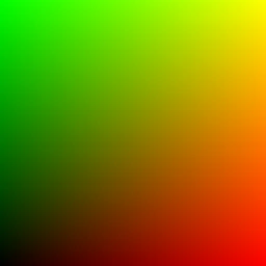


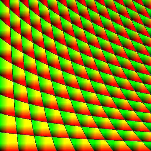
UV Map
2D Coordinate Remapping
This component provides a flexible way to remap pixel positions using a two‐dimensional coordinate system. The input image texture is re‐projected according to U and V coordinates, where U corresponds to the horizontal axis and V corresponds to the vertical axis.
This approach allows for controlled warping, shifting, and reorientation of images — making it a fundamental tool in both image processing and rendering workflows. Whether used for texture projection, procedural pattern design, or creative distortion effects, UV mapping enables a structured method of reshaping how pixels are distributed across the output image.
By defining how input coordinates are mapped to the output space, this UV Map Component acts as a versatile foundation for more complex mapping operations, such as tiling, layering, or non‐linear remapping.
Resources:
Download the .tox files,
Texture Coordinates and Texture Sampling,
Texture Coordinates by FME,
UV Mapping on Wikipedia
Parameters
Sample:
Specifies a TOP input whose resolution will define the output UV Map’s dimensions. Useful for ensuring the UV map matches another texture in size.
Dimensions:
Sets the output resolution manually when no TOP is sampled. Defines the width and height of the generated UV map.
Method:
Determines the coordinate system for the UV map:
Standard (Origin at the bottom‐left corner (0,0)) or
Centered (Origin at the center of the output texture)
Aspect Correction:
Toggles whether the generated coordinates preserve the native aspect ratio of the output texture or are normalized between 0 and 1.
Translate:
Offsets the UV map along the U and V axes, shifting the coordinate space horizontally or vertically.
Rotate:
Rotates the UV map around the pivot point, allowing for reorientation of the coordinate system.
Scale:
Adjusts the size of the UV coordinate space along the U and V axes.
Pivot:
Defines the reference point (U, V) around which transformations such as rotation, translation, and scaling occur.
Outputs
Output 0 – TOP generated UV map.
Updated – 18/5/2026
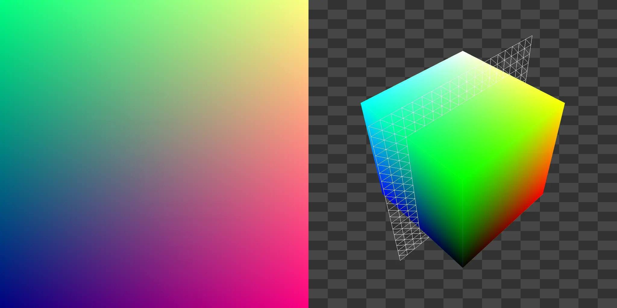
UVW Map
3D Coordinate Remapping
This component extends traditional UV mapping into three dimensions, generating a UVW coordinate field where U corresponds to the horizontal axis, V to the vertical axis, and W to depth. Instead of working in only two axes, the UVW Map allows you to define and manipulate a full three‐dimensional coordinate space for texture projection and spatial mapping.
By incorporating a W axis, this component enables more complex remapping operations such as volumetric textures, layered projections, and triplanar blending. The UVW coordinate field can be rotated along all three axes and stretched or compressed independently, making it a versatile tool for procedural patterning and advanced mapping techniques.
As with UV mapping, the UVW Map operates by re‐projecting the input image into a new coordinate space, but with the additional flexibility of depth‐aware manipulation. This allows for effects and workflows that go beyond simple 2D warping, including pseudo‐3D pattern generation and multi-axis distortions.
Resources:
Download the .tox files,
Texture Coordinates and Texture Sampling,
Texture Coordinates by FME,
UVW Mapping on Wikipedia
Parameters
Sample:
Specifies a TOP input whose resolution will define the output UVW Map’s dimensions.
Dimensions:
Sets the output resolution manually when no TOP is sampled. Defines the width and height of the generated UVW map.
Depth:
Defines the scale of the W axis (depth) in the output UVW Map.
Aspect Correction:
Toggles whether the generated coordinates preserve the native aspect ratio of the output texture or are normalized between 0 and 1.
Translate:
An XYZ offset applied to the UVW coordinate space. Shifts the mapping along the U, V, and W axes.
Rotate:
An XYZ rotation applied to the UVW coordinate system. Allows reorientation of the mapping around each axis.
Scale:
An XYZ scaling factor applied to the UVW coordinate space. Stretches or compresses the mapping independently along each axis.
Outputs
Output 0 – TOP generated UVW Map.
Updated – 18/5/2026
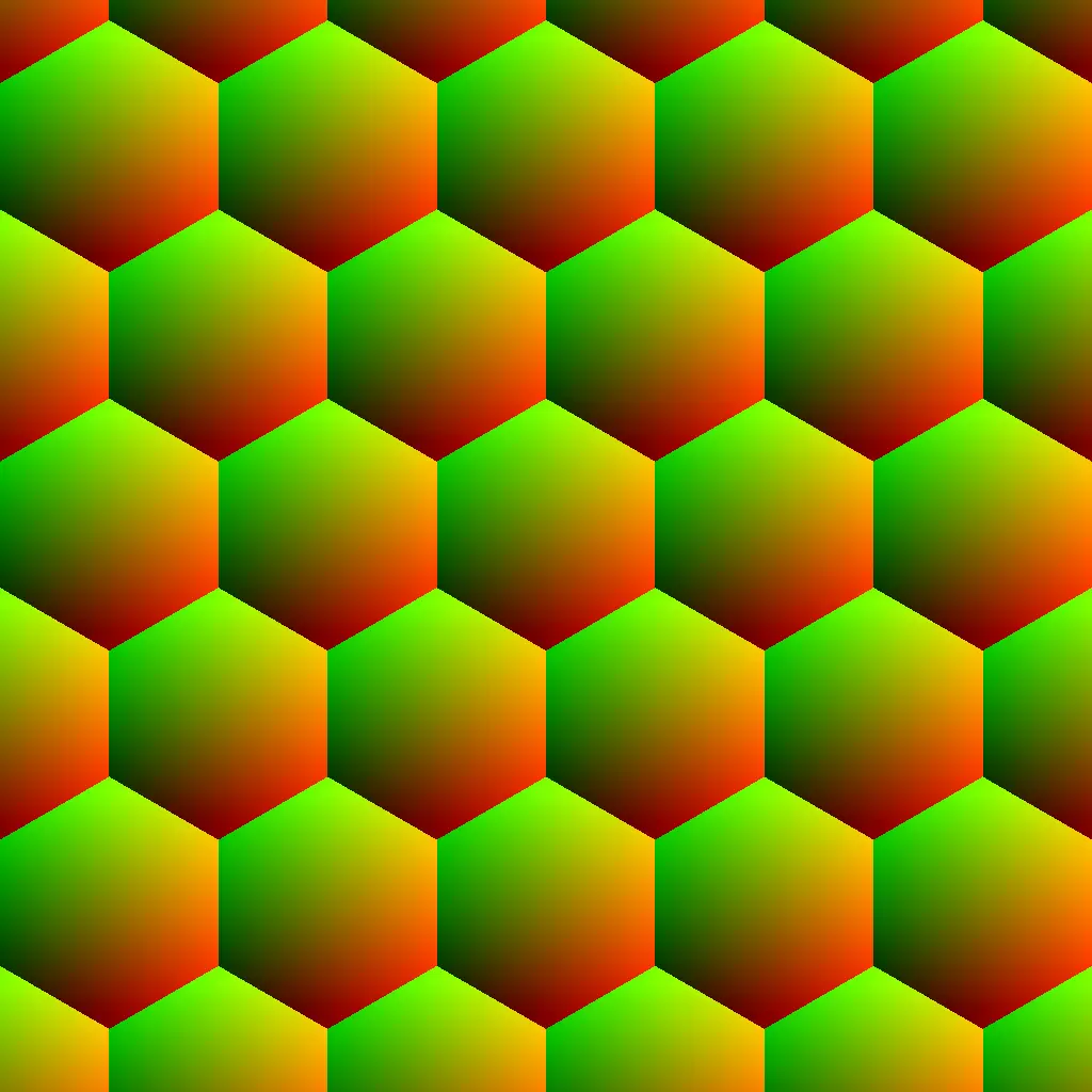
Hex Grid
Hexagonal Tiling UV
This component generates a hexagonal coordinate grid, producing a continuous tiling pattern that can be used for procedural mapping, pattern generation, or texture sampling. Unlike a square or rectangular UV layout, the hexagonal grid introduces six‐way symmetry.
Each hexagonal cell is defined within the UV coordinate space, and the number of cells is determined by the Repeat parameter, which controls tiling density along the X and Y axes. The Margin parameter adjusts the spacing between neighboring hexagons, enabling everything from tightly packed honeycomb structures to spaced, modular layouts.
Resources:
Download the .tox files,
Texture Coordinates and Texture Sampling
Parameters
Sample:
Specifies a TOP input whose resolution will define the output hexagonal grid’s dimensions.
Dimensions:
Sets the output resolution manually when no TOP is sampled.
Translate:
Offsets the hexagonal grid along the U and V axes, shifting the coordinate space horizontally or vertically.
Rotate:
Rotates the hexagonal grid around the pivot point, allowing for reorientation of the coordinate system.
Pivot:
Defines the reference point (U, V) around which transformations such as rotation, translation, and scaling occur.
Repeat:
Defines the number of hexagonal tiles that will repeat across the U and V axes of the output.
Margin:
Controls the spacing between adjacent hexagons. Increasing this value separates tiles with visible gaps, while decreasing it creates a continuous, tightly packed grid.
Outputs
Output 0 – TOP generated hexagonal grid.
Updated – 18/5/2026
UV to Hex Grid
Hexagonal Remapping of UV Space
This component extends the functionality of the standard Hex Grid by allowing any UV Map input to be segmented and restructured into a hexagonal coordinate layout. Rather than generating a tiling pattern from scratch, it adapts an existing UV space — regardless of how warped, scaled, or distorted it may be — and subdivides it into a field of hexagonal cells.
Each hexagon acts as a localized sampling region within the input UV space, providing a way to reinterpret complex or procedural mappings through a structured, six‐way symmetric grid. The result is a UV representation that preserves the original mapping’s topology while imposing a consistent hexagonal tessellation, ideal for generative pattern design, geometric quantization, or stylized image remapping.
Resources:
Download the .tox files,
Texture Coordinates and Texture Sampling
Parameters
Repeat:
Defines the number of hexagonal tiles that will repeat across the U and V axes of the output.
Margin:
Controls the spacing between adjacent hexagons. Increasing this value separates tiles with visible gaps, while decreasing it creates a continuous, tightly packed grid.
In‐ / Outputs
Input 0 – TOP UV map to be remapped.
Output 0 – TOP generated hexagonal grid.
Updated – 18/5/2026
UV Transform
2D Coordinate Transformation
Instead of remapping from scratch, the UV Transform component modifies existing UV maps by applying pivot‐based transformations within the UV coordinate space. This provides precise post‐control over how textures or procedural images are projected.
This component is particularly useful in workflows involving chained mappings or layered projections, where incremental adjustments to UV coordinates are needed to align, tile, or animate textures across multiple surfaces. Used in combination with the UV Map or UVW Map components, the UV Transform serves as a flexible intermediary step for refining complex coordinate manipulations.
Resources:
Download the .tox files,
Texture Coordinates and Texture Sampling
Parameters
Translate:
Offsets the UV map along the U and V axes, shifting the coordinate space horizontally or vertically.
Rotate:
Rotates the UV map around the pivot point, allowing for reorientation of the coordinate system.
Scale:
Adjusts the size of the UV coordinate space along the U and V axes.
Pivot:
Defines the reference point (U, V) around which transformations such as rotation, translation, and scaling occur.
In‐ / Outputs
Input 0 – TOP UV map to be transform.
Output 0 – TOP transformed UV map.
Updated – 18/5/2026
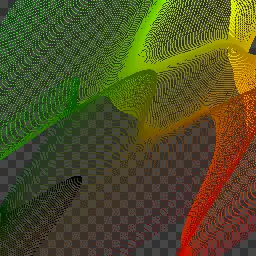
UV Corrector
Local UV Linearization
This component corrects distorted UV maps by restoring local linearity within the UV coordinate field. Rather than globally reprojecting or re‐mapping coordinates, the UV Corrector operates locally — allowing repeated or tiled UV structures to be corrected independently within each repetition.
When UV maps are warped, stretched, or procedurally modified, their red and green gradient fields often lose linear consistency. This loss of structure results in visible artifacts during image remapping, such as warped geometry, bent textures, or uneven scaling. The UV Corrector addresses these issues by re‐linearizing the UV gradients while preserving the original spatial placement and character of the distortion.
The mathematical approach behind this component was shared by Andrei Zelenco, who defined the locally correcting UV gradients via differential analysis as:
Let the input UV map be treated as a vector‐valued function over image space:
Where denotes a pixel position in the image, and and correspond to the red and green channels of the UV map respectively.
The local deformation of this UV field is described by its Jacobian matrix:
This matrix captures how the UV coordinates stretch, shear, or rotate locally with respect to image space.
To correct the distortion, the UV Corrector computes the inverse of the transposed Jacobian and applies it to the original UV vector:
This ability to restore linearity to input UV Maps while preserving the positional intent of the original UV transformation proves to be a powerful differential tool for repairing distorted UV fields rather than replacing them, enabling reversible, high‐fidelity UV workflows in complex procedural mapping pipelines.
Resources:
Download the .tox files,
Texture Coordinates and Texture Sampling,
Andrei Zelenco’s YouTube Channel
Parameters
Edge Handling:
Determines how the edges of the image are treated during convolution. Extends the image to avoid edge artifacts.
Scalar:
Uniformly adjusts the size of the UV coordinate space along the U and V axes.
In‐ / Outputs
Input 0 – TOP Distorted UV map to be corrected.
Output 0 – TOP Corrected UV Map.
Updated – 18/5/2026
UV Inverse Map
Inverse Coordinate Reconstruction
This component computes the inverse of a UV mapping: given any forward UV map that remaps pixel positions, this operator generates the complementary UV field that reverses that transformation.
Formerly, if the original UV map defines a function:
The UV Inverse Map reconstructs the inverse mapping:
Such that:
In other words, the inverse UV map returns each displaced pixel to the location from which it originated.
When applied to an image that was previously distorted via the original UV map, the resulting inverse map restores the image back to its undistorted state, minus any information that was lost in the forward transformation.
This makes the UV Inverse Map a powerful tool for workflows involving reversible warping, bidirectional mapping, UV‐based lenses, and procedural distortions that require a mathematically exact undo.
As the white color of the component suggests, this is an experimental operator and becomes unreliable with UV map inputs larger than 1024×1024.
Resources:
Download the .tox files,
Texture Coordinates and Texture Sampling
In‐ / Outputs
Input 0 – TOP Distorted UV map to be undistorted.
Output 0 – TOP Calculated Inverse UV Map.
Updated – 22/11/2025